
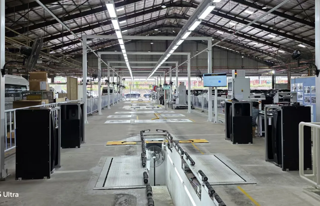
Non-contact Wheel Alignment Vector TV8 (Auto Track Width)
AgencyNon-contact wheel alignment with automatic track width adjustment, made by TechnoVector (Russia)
Product Details
Made in Russia by TechnoVector | Non-Contact Four-Wheel Positioning · Automatic Wheel Track Configuration
Non-contact four-wheel aligner Vector TV8 (automatic wheelbase)
4 groups of 10 cameras | Tilt of the front and rear axles and the number of front beams for 5 seconds | Automatic adjustment of the wheelbase | Safety grating protectionVector TV8 Non-Contact Four-Wheel Locator (Automatic Wheel Gauge Configuration) Complete Machine| 5 s
No fixture, target plate form Front and rear axle tilt and front beam detection beat |
Automatic Wheelbase
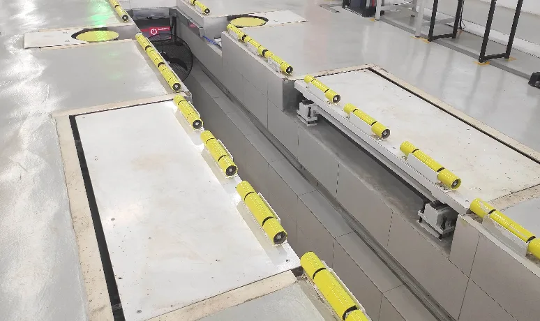
Automatic Wheel Tread Adjustment Below the Turntable Automatically adjust the spacing of the corner panels on both sides according to the model |
± 50°
Turntable angle measurement range, accuracy ± 0.5° Single turntable load ≥ 3000kg |
产品概述
The non-contact automotive four-wheel aligner is a special equipment for measuring and adjusting the wheel position of the assembled vehicle. The equipment positions, measures and determines the four wheels of the car through the non-contact measuring unit, and adjusts online according to the measurement results to ensure that the wheel positioning meets the designed parameters and requirements.Manufactured by TechnoVector in Russia, the Vector TV8 uses non-contact laser measurement and 3D projection irradiation imaging processing technology, up to 8000 points per tire, to perform three-dimensional reconstruction of the tire to determine the front beam and inclination of the tire, with high measurement accuracy, low repeatability error and stable operation.
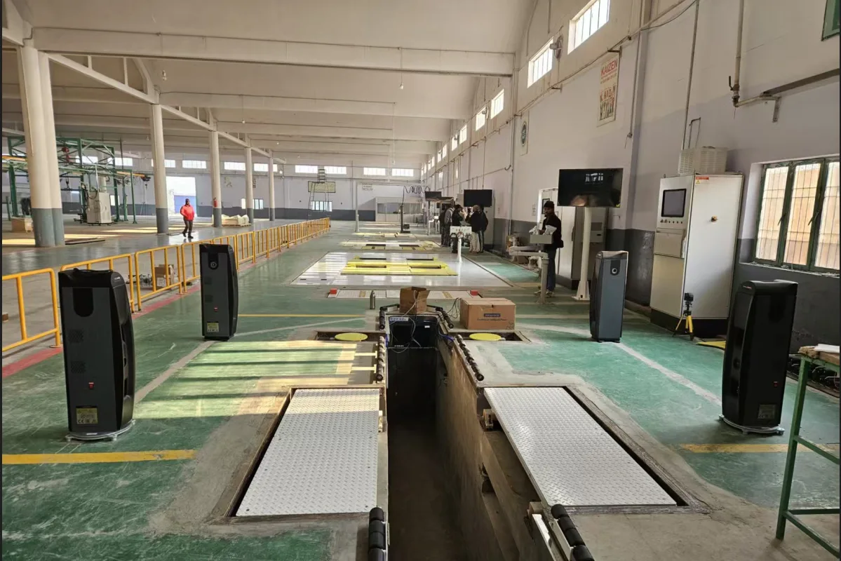
This page is about the Vector TV8 platform.Automatic WheelbaseConfiguration. This configuration sets the wheel track automatic adjustment device below the turntable, which can automatically adjust the spacing between the two side corner discs according to the model wheel track to meet the vehicle measurement within the wheel track range; at the same time, it is equipped with a fully automatic pneumatic turntable system, which can automatically lock and loosen as needed.The two configurations work together to enable the station to complete the conversion and enter the measurement state without manual movement or repositioning of the corner disc when facing multi-model and multi-pitch mixed production, which significantly reduces the station preparation time and reduces the measurement deviation caused by inconsistent manual adjustment. The wheelbase mobile device is equipped with a safety grating in the middle, and the wheelbase mobile device cannot move when someone or other objects are in the middle, providing reliable interlock protection for workers in the pit.
The equipment is fixed with 4 fixed columns, the host system and camera are not exposed, and there is no loss of accuracy caused by moving parts to ensure the accuracy and stability of the measurement; the control part of the locator is controlled by a computer, and the processed test data is transmitted to the computer system in real time, so that the functions and test items of the system are more perfect.This configuration is especially suitable for the end of the vehicle assembly line, the vehicle off-line detection line, and the pass-through positioning station that needs to take into account multiple wheelbase models, helping the vehicle manufacturer to obtain stable and consistent positioning measurement results while ensuring the beat.
Core Strengths
|
■Wheel gauge automatic adjustment device: There is a wheel gauge automatic adjustment device below the turntable, which automatically adjusts the spacing of the corner wheels on both sides according to the wheel gauge of the vehicle to meet the vehicle measurement within the wheel gauge range. The type change no longer depends on manually moving the turntable, and the preparation time for mixed-line production decreases synchronously with the human error. ■Safety grating interlock: A safety grating is installed in the middle of the wheelbase mobile device. The wheelbase mobile device cannot move when someone or other objects are in the middle, and the safety protection of pit workers is solidified into the equipment action logic. ■Automatic locking turntable: The angle measurement range of the turntable is ± 50°, and the accuracy is ± 0.5°; the bearing capacity of each turntable is ≥ 3000kg, the diameter of the turntable is ≥ 600mm, the free floating range in the X and Y directions is ≥ 50mm, and the rotation freedom of the Z axis is ≥ 360°. After measurement, the floating disc is locked, and the vehicle can normally leave the station. ■No fixture, target plate form: No need to install or set any adapter on the wheel, no need to contact the vehicle, it only takes 5 seconds to detect the front and rear axle inclination and front beam data, eliminating the clamping and cart compensation link. |
■4 groups of 10 cameras positioning and detection: The pair of camera groups is fixed in the scanner structure, and the target three-dimensional information is obtained through the depth calculation of two viewing angles, which is the direct landing of the most advanced structured light three-dimensional scanning technology route in the industry. ■Fixed column structure: 4 fixed columns are used, the host system and camera are not exposed, no moving parts bring accuracy loss, and measurement accuracy and stability can be maintained after long-term use. ■Automatic real-time detection and automatic calibration: The equipment program is equipped with automatic real-time detection function and automatic calibration technology, which eliminates the need for periodic calibration of the positioner camera and reduces the workload of line edge calibration maintenance. ■No trolley, no brake required to measure rear inclination: The device adopts advanced structured light 3D scanning positioning technology, no personnel trolley to compensate, and no brake required for rear inclination measurement (rear inclination measurement is optional, maximum steering angle measurement is selected, and configured as required). |
Structure and detail display
|
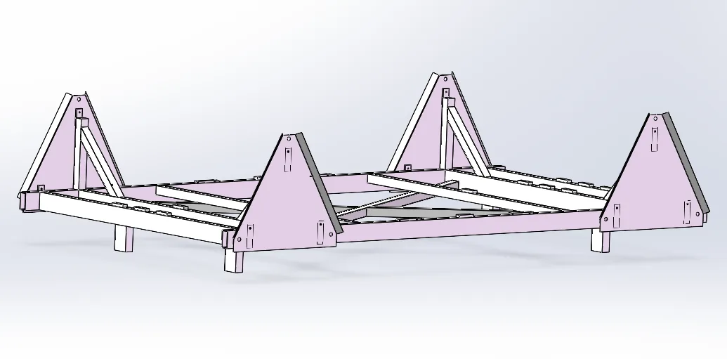
Rendering of left and right corner table assembly |
Wheelbase automatic adjustment mechanism and automatic locking turntable The rotor has a floating function: when the vehicle tires are adjusted, the floating rotor is in a floating state to meet the free adjustment of the vehicle tires; when the vehicle measures the maximum steering angle, the floating rotor is in a floating state, and the wheels do not slide relative to the rotor, and the surface of the rotor has a non-slip design; when the vehicle is measured, the floating rotor is locked, and the vehicle can normally drive out of the station.Below the turntable is the wheelbase automatic adjustment device, which can automatically adjust the spacing of the corner discs on both sides according to the wheelbase, so that the same station covers all models within the wheelbase. The wheelbase movement device is equipped with a safety grating in the middle, and the wheelbase movement device cannot move when someone or other objects are in the middle, so that the device is always controlled during automatic movement. The equipment is very convenient to complete the measurement on both sides of the trench. The monitor on the control cabinet and the operator display in the pit display the measurement value in real time, and the operator can synchronously interpret the data under the vehicle. |
|
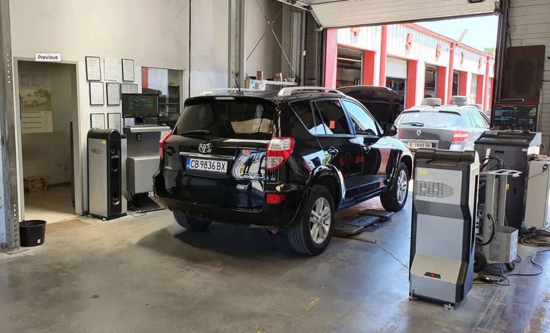
Equipment calibration racks and periodic calibration The equipment is supplied at random, and the factory can perform periodic calibrations to ensure the accuracy of the measurements. Through the calibration procedure, the front beam angle and inclination angle are compensated to the four-wheel positioner for correction. The equipment program itself has an automatic real-time detection function and automatic calibration technology, which eliminates the need for periodic calibration of the positioner camera, so that the calibration work can be arranged according to the factory metering cycle, and does not occupy the production beat. When measuring, pairs of camera sets are installed in a structure called a "scanner": each pair of cameras is fixed in a slightly separated position, and the depth of the object seen is calculated from two images, thereby obtaining the 3D size of the object to be measured. Pairwise cameras operate at fixed, tiny intervals, providing the basis for a complete system that accurately captures every tiny change in angle, as well as the ability to independently measure each wheel. |
Equipment calibration rack (for regular factory calibration) |
Measurement content
Front wheel front bundle (left/right), front wheel total front bundle, front wheel outward inclination (left/right), main pin backward inclination, main pin inward inclination, rear wheel outward inclination (left/right), maximum steering angle, etc. The device is a static measurement and adjustment by means of which the forward and outward tilt of the wheels can be measured repeatedly.
The measurement of the rear inclination angle of the main pin and the inclination angle of the main pin is indirectly measured: by turning the steering wheel left and right, the rear inclination angle of the main pin and the inclination angle of the main pin are calculated and displayed on the liquid crystal display. Measure the real-time data of the whole vehicle, such as the single wheel front beam, total front beam, outward inclination angle, inward inclination angle, backward inclination angle, propulsion angle, steering angle, steering wheel inclination angle, etc., and adjust online according to the measurement to ensure that the wheel positioning meets the design parameters and requirements.
Technical Parameters
Measurement item accuracy and range (for TV8 systems with automatic wheelbase configurations):
| Measurement content | 精度 | Scope | Accuracy Total Measurement Range |
|---|---|---|---|
| Total anterior bundle (front wheel) | 0. 02 | 0. 2 | 0.80 |
| Single anterior bundle (anterior and posterior) | 0. 02 | 0. 2 | 0. 4 |
| Camber angle | 0. 02 | 0.80 |
0.80 |
| Retract Angle | 0. 02 | 0. 2 | 0. 4 |
| Thrust angle | 0. 02 | 0. 2 | 0. 4 |
| caster | 0.05 | ||
| Angle of Inclusion | 0.05 | ||
| Maximum steering angle | 0:08 | 0. 50 | 0. 50 |
| Tilt Back Adjustment | 0. 02 | 0.80 |
0.80 |
Corner disc and automatic wheelbase configuration parameters:
| Item | Specs |
|---|---|
| Turntable Angle Measurement Range | 50 |
| Turntable Angle Measurement Accuracy | 5.0 |
| Carrying Capacity of Single Turntable | ≥ 3000kg |
| Rotating disk diameter | 600mm |
| X, Y free floating range | 50mm |
| Z-Axis Rotation Degrees of Freedom | 360° |
| How to adjust the wheelbase | Automatic adjusting device for the lower wheelbase of the turntable, automatically adjusting the spacing between the corner discs on both sides according to the wheelbase of the vehicle |
| Safety protection | The wheelbase mobile device is installed with a safety grating in the middle, and the wheelbase mobile device cannot move when someone or other objects are in the middle. |
| Turntable locking method | Fully automatic pneumatic turntable system, which can be automatically locked and loosened as needed; the surface of the turntable has a non-slip design |
| Camera Configuration | 4 groups of 10 cameras |
| Column form | 4 fixed columns fixed (mainframe system and camera not exposed) |
Scope of Supply
| Non-contact four-wheel aligner system | Configuration Content |
|---|---|
| Measurement Unit Column Assembly | Includes column side cover and bottom cover |
| Sensor assembly | Includes camera/target board/laser emitter |
| Dedicated computer mainframe | Running platform with positioning program |
| Program suite | Includes locator and dongle |
| Cable assembly | Including power cord, connecting cord |
| Cable covers and fasteners | Random Package |
| Liquid Crystal Display | Random Package |
| Front axle adjustment turntable and rear axle side slide assembly | Automatic wheelbase adjustment device under the turntable included |
| Control valves and cables/air pipes | Pneumatic control system matching |
| Pit Display | For simultaneous interpretation of data by operators in the pit |
| Monitor + monitor mounting bracket | Random Package |
| Printer | Used to locate data for print retention |
| Steering wheel level | Used to adjust the steering wheel level |
| Wireless scanner | Used to enter Vin and model information |
Process Workflow
- Vehicle preparation: Park your vehicle in a guided position ready for pickup.
- Vehicle information entry: The operator uses the barcode scanner to enter the VIN code, and the selection or program automatically identifies the model.
- Vehicle entry: Slowly drive the vehicle into the platform.
- Position compensation: The program automatically completes the compensation when the vehicle enters.
- Front beam and inclination: After the vehicle is in place, the measuring unit automatically displays the inclination and the angle of the front beam, and waits for the commissioning personnel to debug.
- Rear inclination measurement (option): Enter more measurements, select the rear inclination measurement, install the brake lock, release the corner wheel and rear skateboard, hit the direction as instructed by the software to the specified position and stop, after completing one by one, return the steering wheel to the right position.
- Maximum steering angle measurement (direction selection): Enter more measurements, select the rear inclination measurement, and after completing the rear inclination measurement, follow the software prompts to continue rotating the steering wheel to the most extreme position of the machine and hold it, and after completing one by one, return the steering wheel to the right position.
- Data viewing: Click on the measurement to view the vehicle location data.
- Steering wheel fixation: Install the steering wheel level meter, adjust the steering wheel level, and install the steering wheel lock fixation.
- Vehicle adjustment: Follow the software prompts to adjust the vehicle chassis so that the positioning data is within the green qualified range.
- Data Print Save: Print out the adjusted data and save it in the customer database.
- Vehicle exit: Remove the steering wheel level, steering wheel lock, and brake lock, and the vehicle slowly leaves the platform.
The complete test time of the equipment is 70s, in addition to the entry time (about 30s), model data entry (about 30s), steering wheel fixation (about 10s) and vehicle exit. The wheelbase automatic adjustment device and the automatic locking turntable complete the preparation of the spacing between the two side corner discs according to the model before the vehicle is driven in, so that the above beats can remain stable under multi-model mixed-line conditions.
Scenario/Project Case
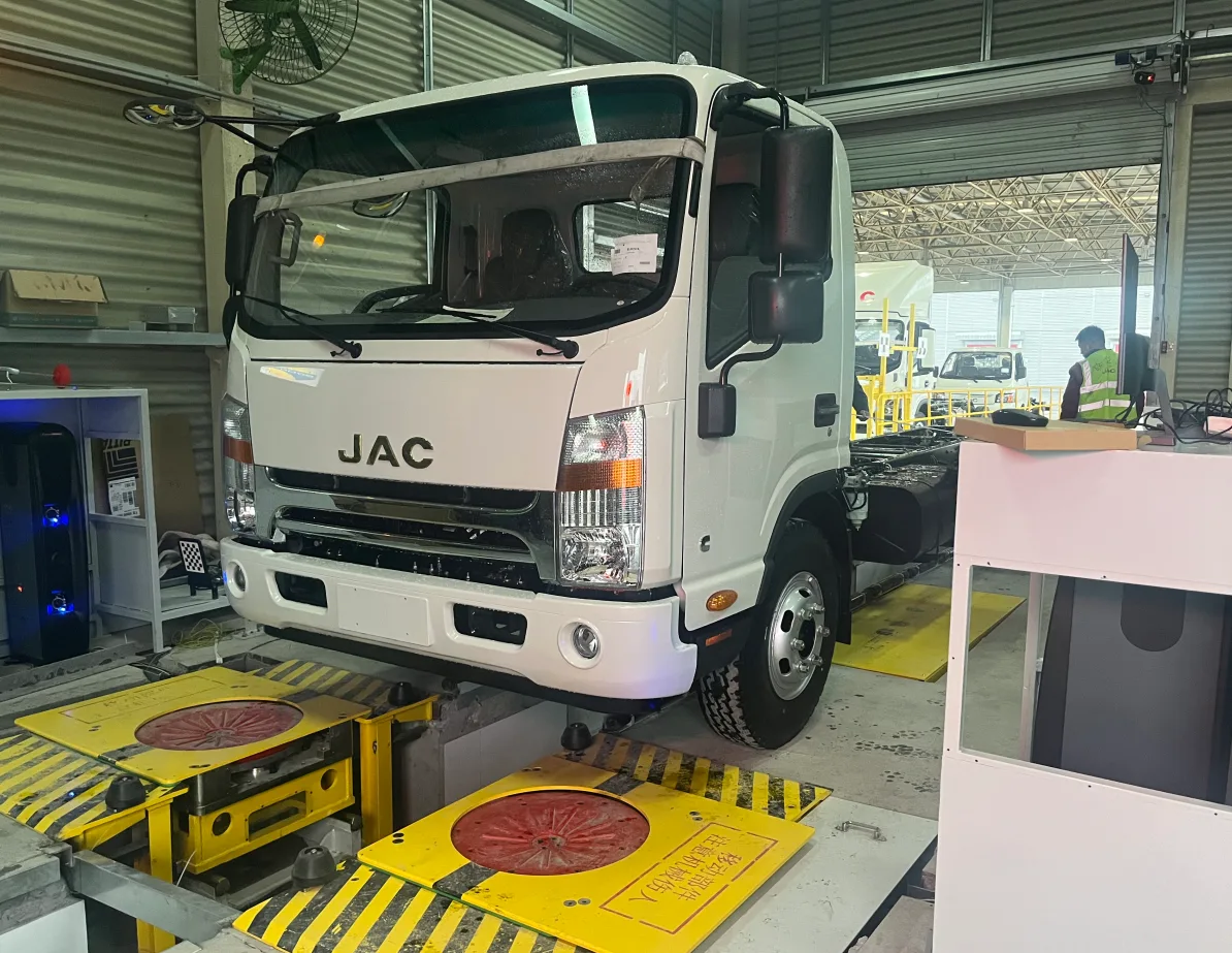
The Vector TV8 (automatic wheelbase configuration) is mainly for the off-line detection station at the end of the vehicle assembly line, the four-wheel positioning adjustment station of the vehicle factory, and the pass-through detection line with high compatibility requirements for multi-wheelbase models. The configuration has been put into use at several vehicle projects at home and abroad, including:
|
Toyota Plant, Russia |
JAC |
KD Plant, Chery Pakistan |
Examples of listed projects include: Toyota Factory in Russia, Kazakhstan, Jianghuai Automobile, Chery Malaysia KD Factory, Chery Pakistan KD Factory. The above projects cover the positioning adjustment and offline testing stations of passenger car manufacturers, which can provide reference implementation experience for the construction of similar stations in our company.
Support
Warranty: One year free warranty and lifetime discount service for the hardware equipment and network system provided. During the free warranty period, any damage caused by the quality and technical failure of the equipment itself, the installation process, etc., shall be repaired and replaced by our company free of charge.
Software upgrades: The latest software updates or upgrades are available free of charge for life.
Personnel training: Provide on-site training services to user operators and technicians, so that operators can master the operation and use of all equipment software, so that technicians can master the working principle of the entire system and the diagnosis and maintenance of common faults. After the installation of each project is completed, an engineering technician can be left to provide on-site guidance according to the situation to ensure that the operators and technicians of each position of the user can be qualified to evacuate after their work.
Repair response time: After receiving the call from the user, the repair response time is within 4 hours, and the on-site time is within 24 hours.
Contact us
Beijing Taiyuanxiang Technology Co., Ltd.
Phone: 010-89780650 Mobile: 18611929790 (Li Yongpo)
Email: liyongpo@taiyuanxiang.cn
Address: Room 3027, Building 1, Hongfu No. 10, Beiqijia Town, Changping District, Beijing
Service content: complete machine sales, installation and commissioning, calibration and accuracy check, operation training, after-sales maintenance and spare parts supply
Note: The product pictures, parameters and function descriptions on this page are compiled from the product technical data and are used for product introduction only. The appearance, configuration and technical parameters of the product will be updated without notice. The specifics shall be subject to the physical and contractual agreements.Related Products
View All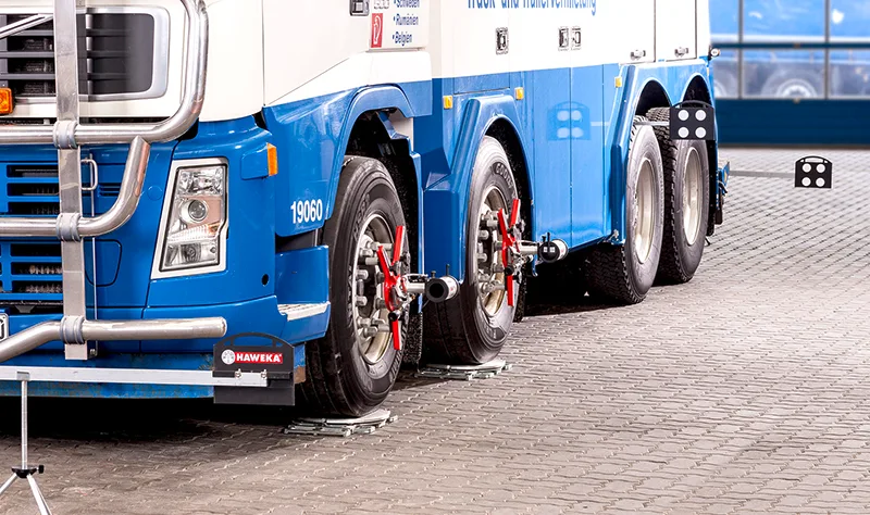
HAWEKA AXIS4000 Mobile Truck Wheel Alignment System
Wireless infrared camera measuring heads referenced to the vehicle centre line; no rim run-out compensation, no lifting required; approx. 10 minutes for a two-axle truck
Learn More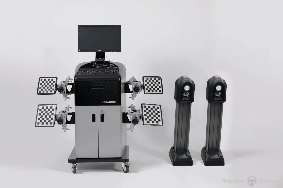
Drive-through Wheel Alignment VECTOR-7202MAB (Russia)
Drive-through wheel alignment system for inspection lines and production line online configuration
Learn More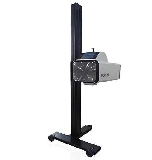
Headlight Tester MQD-3B (Zheda Mingquan)
ARM digital image processing with CCD and touch screen; 0-120,000 cd, optical axis error within ±3.5 cm/dam; suitable for halogen, HID and LED headlights
Learn More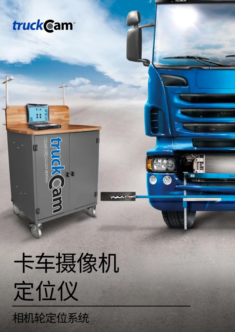
TruckCam Camera Wheel Alignment System (Sweden)
Camera-based wheel alignment and frame inspection system for commercial and heavy vehicles
Learn MoreMore in This Category
View All- HAWEKA AXIS4000 Mobile Truck Wheel Alignment System
- Drive-through Wheel Alignment VECTOR-7202MAB (Russia)
- Headlight Tester MQD-3B (Zheda Mingquan)
- TruckCam Camera Wheel Alignment System (Sweden)
- Headlight Tester MQD-6B (Zheda Mingquan)
- Truck Wheel Alignment Hunter DSP760TCX (USA)
- Headlight Tester SAM2000 (LITE Belgium, Rail Type)
- Wheel Aligner JohnBean i-Aligner Platinum³
- Headlight Tester Calibrator (MQB-1B)
- Wheel Alignment System CEMB ARGOS (Italy)