
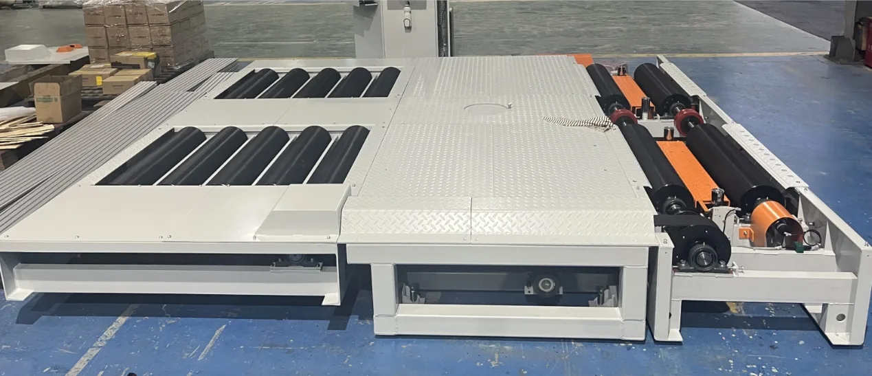
Four-Wheel-Drive Speedometer Test Bench
Oem Eol Testing EquipmentRoller-based road simulation test bench for vehicle speedometer verification. Supports FWD, RWD and 4WD vehicles, with a front-rear axle synchronizing mechanism and a gear-sleeve clutch, dual imported high-precision speed sensors, 0-80 km/h measuring range, LCD TV display and wireless remote blind-test reporting.
Product Details
4WD Speedometer Test Bench
Roller analog road surface · Front and rear axle synchronization · Front/rear/four-wheel drive universal · 0 ~ 80km/h speedometer detection
Four-wheel drive speedometer test stand (live shooting)
4WD full compatibility test
1 set of front and rear axle synchronization mechanism + 1 set of gear sleeve clutch, which can be controlled synchronously or separately, and supports front-wheel drive, rear-wheel drive vehicle and four-wheel drive vehicle speedometer detection.
Dual Velocimetry - High Accuracy
Each front and rear axle roller is equipped with a set of imported brand high-precision speed sensor (encoder), roller Φ216 × 1000mm knurled surface, speed measurement range 0 ~ 80km/h.
Automatic blind test declaration
Equipped with a wireless remote control, the system automatically determines that the speed is stable for 3 seconds. The LCD TV displays commands and data on a large screen, and the actual value and the percentage of the detected value can be directly displayed at 40km/h.
产品概述
The four-wheel drive speedometer test bench is a device that simulates the road surface with a roller, uses the principle that the linear speed of the wheel and the roller is the same when there is no relative slippage, and measures the error of the speed representation value of the car through a speed sensor synchronized with the roller.
The speedometer is an important meter that provides information on the speed of the car. The driver can correctly grasp the speed during the journey, which is the key to improving transportation productivity and ensuring safe driving. In order to ensure driving safety, the speedometer needs to be regularly inspected and verified, which is of great significance to reduce traffic accidents, reduce injuries to passengers and pedestrians during the accident process, and improve traffic safety.
The equipment supports front-wheel drive, rear-wheel drive, and four-wheel drive vehicle detection: the front-wheel drive vehicle is detected on the front axle, the rear-wheel drive vehicle is detected on the rear axle or the front axle, and the four-wheel drive vehicle is synchronously detected through the front and rear axle synchronization mechanism. The detection process is automated, wireless remote control is adopted, and operation is simple.
Core Strengths
- Support front-wheel drive, rear-wheel drive, four-wheel drive vehicle speedometer detection, one device covers a variety of models.
- LCD TV large screen display operation instructions and test data, the test process is automated, wireless remote control operation is simple.
- When the test value is 40km/h, the percentage of the actual running value and the test value can be calculated and displayed.
- The surface of the roller is knurled to meet the friction requirements of the tire; the diameter of the roller is 216mm and the length is 1000mm.
- The equipment is equipped with a lifting mechanism to facilitate vehicle entry and exit.
- 1 set of front and rear axle synchronization mechanism to ensure that the front and rear axles are synchronized during four-wheel drive measurement.
- 1 set of clutch (gear sleeve clutch manufactured by precision machining with Japanese proprietary technology) to achieve pneumatic control of front and rear shaft synchronization or separation.
- 2 sets of high-precision speed sensors, installed on the front axle and rear axle roller respectively, the sensors are imported brands.
- With a safety wheel stop mechanism, the wheel can block the tire when it is swinging left and right, which plays a safety and protection role.
- The roller locking device is synchronized with the lifter: the lifter is raised and the roller is locked at the same time, and it is released when descending to prevent the wheel from slipping on the roller when leaving the car.
- Lifter protection: The lifter is only allowed to rise after the drum rotation speed is lower than the set value (e.g. 5km/h).
- The pit cover plate is connected to the equipment with countersunk head screws, and the cover plate is a non-slip surface.
- Equipped with 1 set of speed strobe meter for speed table calibration and inspection.
- Equipped with 1 set of remote control for blind detection of speed declaration, and support for speed stability judgment (automatic determination of speed declaration for 3 seconds).
- 1 set of brackets and trays are available to hold operating devices such as remote controls.
Equipment composition
The four-wheel drive speedometer test bench is mainly composed of a control system, wheelbase adaptation mechanism, front and rear synchronization mechanism, roller, driver auxiliary display device, driver operation device, etc.
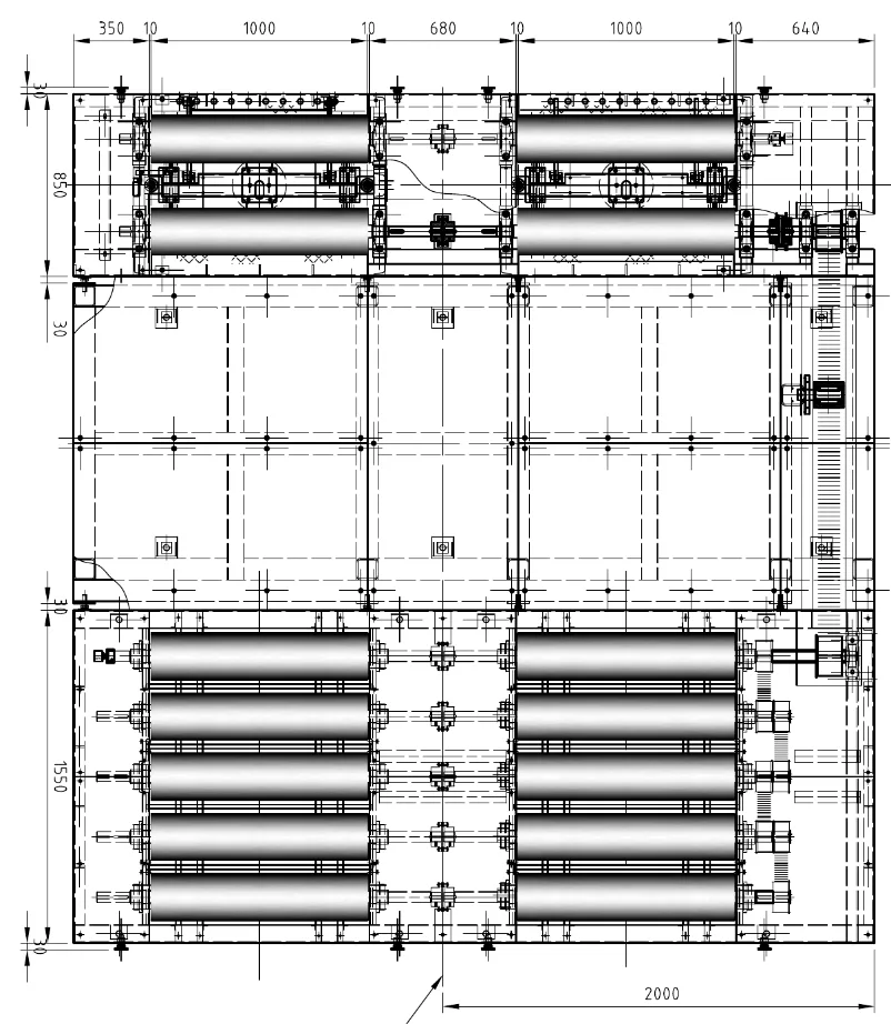
Figure 1 Four-wheel drive speedometer test bench layout (dimensions for reference)
- Steel Structure Cover:1 complete set of test bench supports steel structure and pit cover to meet all bearing requirements, and the pit cover is a non-slip surface.
- Front axle speed table host:1 set, mainly composed of 4 rollers, the surface of each roller is knurled, the diameter of the roller is 216mm, and the length is 1000mm.
- Rear axle drum set:1 set, consisting of 10 rollers, the surface of each roller is knurled, with a diameter of 216mm and a length of 1000mm. Each group of drums is driven by a synchronous belt (right side of the direction of entry), and the first group of drums in the rear axle part and the second group of drums in the front axle part are also driven by a long synchronous belt. Underneath the roller is mounted a brake device that, when ventilated, brakes the roller upward so that the vehicle enters and exits the speed table.
- Clutch1 set of gear sleeve clutches manufactured by Japanese proprietary technology precision machining, mainly through pneumatic control of the front axle speed table host and rear axle roller set.
- Tension device1 set, located under the long timing belt connected by the front and rear axles. When the long synchronous belt loosens, tension it to prevent slippage of the synchronous belt and ensure synchronization.
- Speed encoder:1 set of drum speed measuring encoder, installed on the right side of the first set of drums of the front axle speed table host along the direction of car entry, connected with the first set of drums for speed testing.
- Lifter:2 sets, located between the two roller sets of the front axle speed table host. When the car is driven up or down the test bench, the lifter is raised, and when the wheel is positioned between the two rollers, the lifter is lowered so that the wheel falls on the roller; while the lifter is raised, the brake device is driven upward to brake the roller.
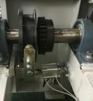
Figure 2 Clutch
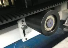
Figure 3 Tensioning device
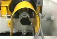
Figure 4 Speed encoder
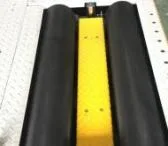
Figure 5 Lifter
PNEUMATIC SYSTEM
The pneumatic control principle of the equipment includes the filter relief valve part, the clutch control part, the rear axle brake control part, and the front axle lift control part.
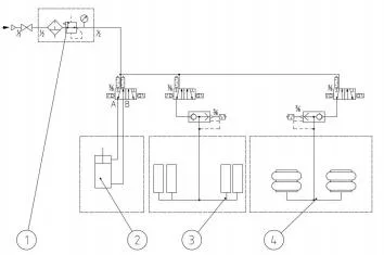
Figure 6 Pneumatic Control Principle (1 Filter Pressure Reducing Valve 2 Clutch Control 3 Rear Axle Brake Control 4 Front Axle Lift Control)
Structural General Drawing and Detection Principle
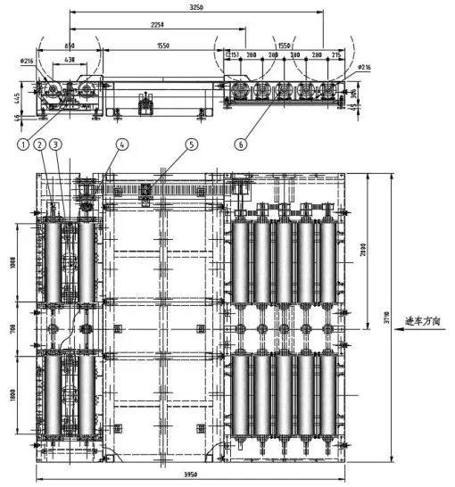
Fig. 7 General structure (1 Front axle speed table host 2 Encoder 3 Lifter 4 Clutch 5 Tensioner 6 Rear axle roller set)
When the vehicle is inspected, the inspected car is placed on the speed bench, and the rotating wheels drive the drum to rotate. The linear velocity V (km/h) of the outer circular surface of the drum is satisfied with the diameter D (mm) of the drum and the rotational speed n (r/min) of the drum.
Speed bench roller diameter D = 216mm. When the linear velocity V of the outer circular surface of the drum is 40km/h, the rotational velocity of the drum is about 981 r/min.
When the car drive roller rotates, the encoder mounted on the roller shaft is driven to rotate synchronously and generate a pulse signal. The computer calculates the linear velocity of the outer circular surface of the roller and displays it. Since the sliding between the wheels of the car and the roller can be ignored, the value of the linear velocity on the surface of the roller is regarded as the actual driving speed of the car under inspection.
There is a certain error between the speed value measured by the speed bench and the indicated value of the vehicle speedometer. The main reasons are: ① The working accuracy of the vehicle speedometer is affected by the size of the tire rolling radius; ② The error caused by the speedometer itself for a long time will also cause the error between the actual driving speed and the speedometer.
GB 7258-2017 "Technical Conditions for Motor Vehicle Operation Safety" stipulates that when the indicated value (V1) of the speedometer of the vehicle under inspection is 40km/h, the indicator value (V2) of the instrument is qualified within the range of 32.8km/h ~ 40km/h.
(II) Main technical parameters
| Parameter Name | Parameter Value |
|---|---|
| Rated Load Mass | 3 t |
| Velocimetric range | 0-80 km/h |
| Drum size (diameter x length) | Φ216 × 1000 mm |
| Front axle roller center distance | 430mm |
| Rear Axle Drum Set Spacing | 280mm |
| Inner and outer span | 700-2700mm |
| Fit to wheelbase range | 2100-3100mm |
| Use air pressure | 0.5 to 0.8 MPa |
| Power Supply | Input voltage: AC220V±10%, 50Hz |
| (Length x Width x Height) | 3950 x 3710 x 445 mm |
| Calibration Allowed Relative Error | < 1% (40km/h calibration point) |
Control System
The control system is designed by Beijing Taiyuanxiang Technology Co., Ltd. according to the electrical characteristics of the speed table and the characteristics of the automotive ECU. It is an intelligent control system. The electrical part uses imported or joint venture brand components to ensure the reliability of system operation. The main part is Advantech Industrial Computers and Siemens PLC.
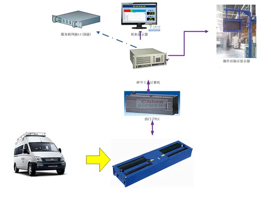
Figure 8 Schematic of the electrical structure of the system
- The system uses Advantech Industrial Computer as the main control computer.
- The system uses the Siemens PLC S7-1200 series as the DI and DO equipment to control the speed table.
- The system uses the PLC S7-1200 series as the frequency acquisition module, and inputs the speed signal into the computer for processing after conditioning.
- The system uses the remote control as a speed declaration signal to communicate with the computer.
- The system uses a splitter to divide the display signal to the LCD TV and instruct the operator to operate it.
- The system has a complete network interface, which can start the test through network control, and generate the test results into a result file.
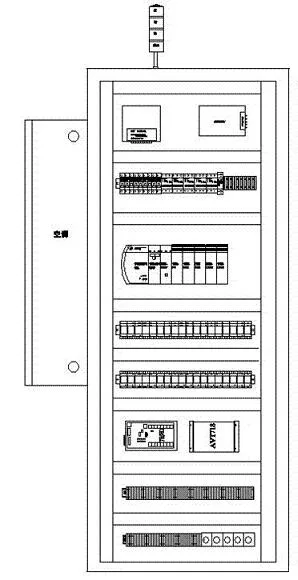
Figure 9 Computer control cabinet
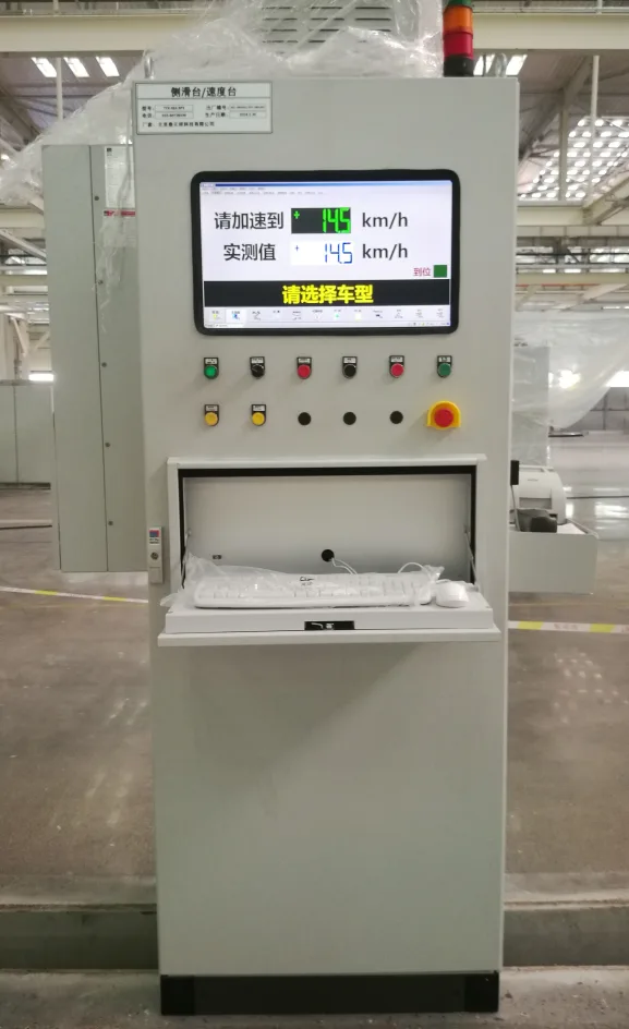
Figure 10 Test console and driver auxiliary display terminal
Speed Stage Software
The speed platform software is independently developed and designed by Beijing Taiyuanxiang Technology Co., Ltd. It is developed by software personnel who have been engaged in automobile testing for many years. The software is powerful, stable and reliable. In addition to providing detection functions, the software also has functions such as parameter configuration, data query printing, and network interface.
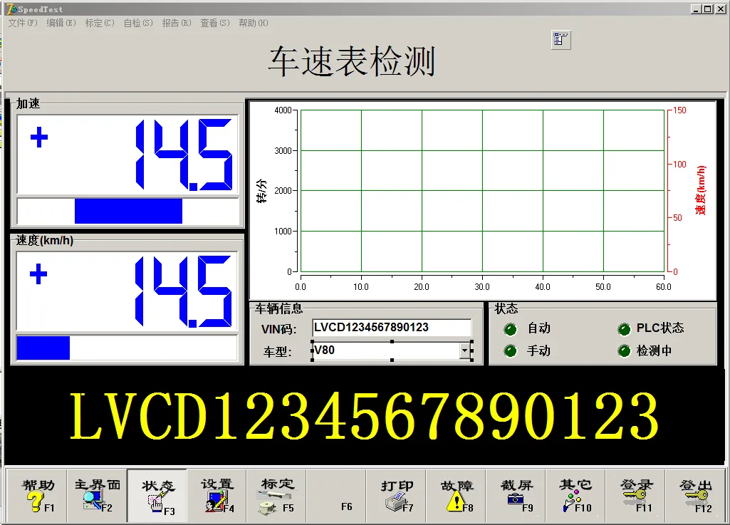
Figure 11 Speed bench detection software main interface (speedometer detection)
Workflow
① PlacementDrive the vehicle straight to the inspection table, manually enter or scan the Vin code, and the vehicle's front axle is parked in the middle of the speed measuring drum.
② Lower the lifterThe lifter descends and the wheel falls on the roller.
③ Accelerated samplingStart the car to accelerate slowly. When the speedometer indicates 40km/h, maintain 3 ~ 5s or press the remote control to declare, the software measures the current actual speed, the system stores and prints the test results, and decelerates and stops.
④ ExitLift the vehicle out of the table by lifting the lifter or locking roller.
Operating Procedures and Maintenance
Preparation before operation
- Check that all parts of the cable should be intact, and all connectors and plugs should be connected reliably without loosening.
- The power supply used should be AC220V ± 10%.
- The lifter is working properly; the pneumatic components are connected tightly, and there is no air leakage.
- Turn on the power of the control instrument and preheat for more than 10 minutes.
- The water, mud, sand and small stones in the tread pattern on the inspected automobile tire shall be cleaned, and the tire pressure shall meet the regulations.
Precautions for application
- When the test needs to be stopped during the test, all in-progress actions must be stopped first.
- Before testing, check whether the condition of the vehicle meets the test bench test conditions, and drive straight to the test bench.
- Standing personnel are not allowed in front of and on either side of the vehicle during the inspection.
- The drum cannot be rotated until the lifter is lowered into place.
- During the test, the speed should be increased gently and the steering wheel should be gripped well; after the test, the brake pedal should not be trampled to stop the roller from rotating.
Care and Maintenance (Key Points)
- The control system device should not be subjected to moisture, vibration, heat and strong direct sunlight; clean all parts after each shift, and check once a month for damage to each connecting wire and loose joints.
- Add lubricating oil or grease to all bearings quarterly while tightening the roller bearing set bolts; perform a thorough cleaning of the encoder and photoelectric switch.
- Perform a calibration check of the accuracy of the whole machine every six months or one year (depending on the use).
- Check the tension of the long timing belt every week. If it is too loose, the timing belt can be tensioned by adjusting the position of the tensioning wheel to prevent tooth loss and slipping.
- Regularly check the coordination between the front axle roller brake device and the lifting mechanism, the braking effect of the rear axle roller brake device, whether the filter pressure reducing valve is normal and drains water in time; check whether the air path is leaking every day.
calibration
Tools: Digital frequency astigmatometer. Method: Make a white mark on the drum, align the dispersion meter with the white mark, and use the car to drive the drum to rotate. When the indicated speed on the instrument is always 40km/h, multiply the frequency signal of the dispersion meter by the diameter of the drum (216mm) and convert it into a linear speed signal, and then calculate the relative error between this speed and the speed of 40km/h. If it is less than 1%, it is qualified.
Contact us
Beijing Taiyuanxiang Technology Co., Ltd.
Phone: 010-89780650 Mobile: 18611929790 (Li Yongpo)
Email: liyongpo@taiyuanxiang.cn
Address: Room 3027, Building 1, Hongfu No. 10, Beiqijia Town, Changping District, Beijing
Disclaimer: The technical parameters, configurations and pictures on this page are organized according to the product technical scheme and are used only for product introduction. Due to the continuous improvement of products, the actual supply is subject to the technical agreement and contract signed by both parties; the parameters contained on this page are not taken as the basis for acceptance.
Related Products
View All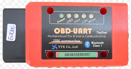
OBD Communication Board (Vehicle Bus Diagnostic Module)
OBD vehicle bus diagnostic module supporting K-Line, CAN, CANFD and DOIP. 6x CAN/CANFD, 1x K-LINE/LIN and 1x DOIP Ethernet diagnostics, industrial Bluetooth plus RS232 wired dual mode, 9-36V wide voltage, automatic OBD pin conflict switching and anti-unplug reminder, designed for vehicle EOL electrical inspection.
Learn More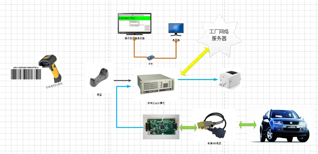
Vehicle Electrical Inspection System (EOL Electrical Test)
OBD decoding board with Advantech IPC and wireless barcode scanner covering ICE and EV electrical tests; DTC reading and localisation, airbag VIN writing; central server management with MES/SAP interface
Learn More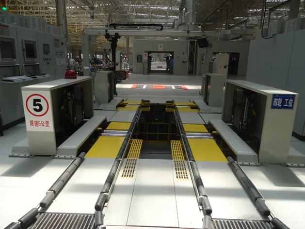
Passenger Car Wheel Alignment Machine
Non-contact 3D laser with 8-camera dynamic measurement, ±0.02° accuracy, for car and truck EOL inspection
Learn More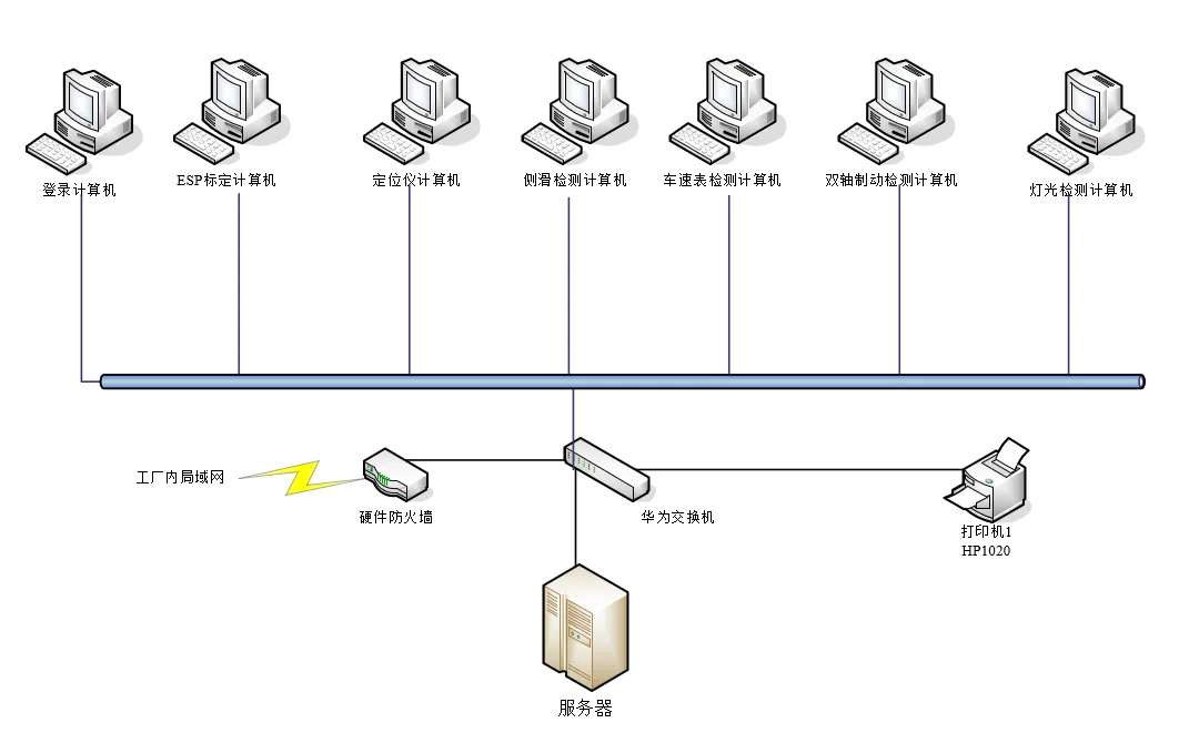
Vehicle Test Line Networking System (DMS Data Acquisition)
Workshop devices networked to a master PC with SQL Server database and report printing; automatically collects alignment, headlight, side-slip, sound level, speed, brake, ABS, axle load and emission data, capacity 1,000,000 vehicles
Learn MoreMore in This Category
View All- OBD Communication Board (Vehicle Bus Diagnostic Module)
- Vehicle Electrical Inspection System (EOL Electrical Test)
- Passenger Car Wheel Alignment Machine
- Vehicle Test Line Networking System (DMS Data Acquisition)
- Twin-Axle ABS Brake Test Bench (Reaction Type)
- 360 Surround-View Camera Calibration System
- Twin-Axle Speedometer Test Bench
- Vehicle Profile Meter (Non-contact Body Contour Measurement)
- Commercial Vehicle ABS Brake Test Bench
- Inspection Line Network Management System